Electronic Devices
RRNSOFT
We measure and beyond..
A product development company.
The Principle
Magnetic flow meters, often called "mag meter"s or "electromag"s, use a magnetic field applied to the metering tube, which results in a potential difference proportional to the flow velocity perpendicular to the flux lines. The potential difference is sensed by electrodes aligned perpendicular to the flow and the applied magnetic field. The physical principle at work is Faraday's law of electromagnetic induction. The magnetic flow meter requires a conducting fluid and a nonconducting pipe liner. The electrodes must not corrode in contact with the process fluid, so very often stainless steel sensors are used. The applied magnetic field is pulsed, which allows the flowmeter to cancel out the effect of stray voltage in the piping system. RRNSOFT & ECA Systems has successfully developed flowmeters exclusively to measure the flow rate and other vital informations from effulent removed water.
How the system works
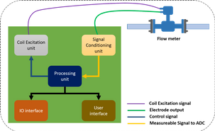
Electromagnetic flow meters are primarily embedded systems which are divided into seven functional units as the right.
Flow tube houses the field coil and the electrodes which are in direct electrical contact with the moving conductive fluid. The electrode picks up the voltage present in the fluid. The electrode element is an important consideration. There are many options available for electrode elements with different temperature drift, corrosion rate and electrode potential characteristics including Platinum, SS etc. Selection of the same depends on the type of fluid being measured along with the required durability.
Coil excitation unit generates electric current which excites the field coils according to the control signal from the processing unit in order to generate the controlled magnetic field. Different type of excitation signals and their construction are described in next section.
Signal conditioning unit translates the flow tube electrode output into a significant measureable signal that is to be used for flow measurements. Instrumentation for the same is explained in the later sections.
Processing unit is the heart of electromagnetic flow meter. The control signal for the coil excitation unit is provided by the processing unit. It also works on the signal obtained from the conditioning system with various statistical and mathematical formula and provides the final flow reading to the IO and user interfaces.
IO interface supports providing the flow information to the existing external device. There are many output formats available to communicate with the external devices such as pulse output, current or voltage output, relay output, RS485/RS232 serial communication etc. In addition to the output interface, flow meter may also support interfacing the external transmitters, sensors or transducers as a value added option. With these external sensor or transmitter interface, the flow meter can also provide additional information such as temperature, pressure etc.
User interface such as LCD display, keypads, LEDs etc provides manual operation such as setting, editing the flow meter configurations at the field.
Power Supply Unit provides a stable power supply as it determines the quality of the measurements made. The magmeter might be powered from an AC source or from a battery. Smart power management and component selection is necessary for long battery life for battery magmeters.
Flow Instrumentation
In this section, we will discuss about electromagnetic flow measurement and instrumentation for the same. Other units of the flow meter like IO, User Interface and Power supply are not in the scope.
Coil Excitation
There are different techniques available for exciting the field coil each with varying degrees of complexity and error correction as follows
DC current excitation: Oldest excitation technique used to generate the magnetic field by driving the field coil using a constant DC current. In this type of technique, due to inherent error build up, the quality of measurement is limited.
AC sine wave: In this technique, the field coils are driven with AC excitation. This technique has disadvantages such as electromagnetic disturbance and zero point drift.
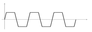
Low frequency DC rectangle: Most commonly used technique in which the field coils are excited using constant amplitude, alternating direction current to achieve the low zero point drift.
Tri-state low frequency DC: This type of excitation is similar to the low frequency dc rectangle excitation, but the duty cycle is reduced to about half of that of the rectangle. With this method, the zero point calibration is done during the absence of the excitation current. This type of excitation consumes lesser power too.
Dual Frequency: In this type, usually 1/8 of power line frequency is modulated with higher frequency to minimize the noise effectively. This method provides fast response but its operation is complex compared to that of the previous excitation types.
As mentioned earlier, there are many ways to achieve the each above excitation techniques. Of them, low frequency DC rectangle excitation using MOSFET H-bridge with constant current sink circuit is most commonly used.
Transistor or MOSFET H-bridge can be used to switch the direction of the constant current flow. With MOSFET H-bridge circuit, the field coils will be excited in the positive and negative phase simultaneously. The control signal for the H-bridge is provided by the processing unit. The excitation frequency will be 1/16, 1/10, 1/8, 1/4, or 1/2 of the power line frequency.
Low Frequency Excitation
The excitation current to the field coil should be constant and the level may vary according to the diameter of the flow pipes. A current level from around 150mA for smaller diameters to upward of 1A for larger diameters may be required.Since the current should be constant, a reliable and accurate current sink circuit is needed. The traditional method of constant current sink is using a linear regulated current sink circuit. This circuit requires a fixed voltage reference, operational amplifier, transistor and the current setting resistor. This circuit together with the H-bridge provides good performance with low noise. But the disadvantage of this circuit is the power loss due to the linear drop of the large current across the large voltage. Hence heat sink is required which adds extra costs and PCB area.
The following figure depicts an example circuit model of the coil excitation unit using linear regulated current sink circuit.The best alternative of this circuit is the constant current sink with switch mode power supply. This technique eliminates the losses and improves the system performance.
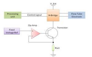
Magmeter Coil Excitation Circuit
With some modifications, the above circuit can be extended to use with tri-state and dual frequency excitation.
Signal Conditioning
Signal conditioning circuit requires the most careful design of the instrumentation as it determines the accuracy of the measurement. The e.m.f induced in the fluid is received by the sensor electrodes in the flow tube and carried over shielded copper cables to anywhere from few centimeters to few meters. The signal has following features:
Based on the flow velocity, the signal induced can vary from few uV to few mV there by with a dynamic range more than 1000.
Due to the effects like electrochemical reactions and others, there is a large amount of noise introduced in the flow tube.
With a large cable length between the tube and electronics, more noise is introduced from other sources like power cables, adjacent meters and systems etc. In certain environments, even when a person walks over the cable, noises are induced.
Information related to the flow is available from the difference of the voltage between electrodes. To handle such a sensor signal, irrespective of the electrode material, the signal conditioning circuit must perform the following tasks,
Rejecting the common mode voltages
Amplifying the low level electrode signal
Filtering the DC component and further amplification
Level shifting to identify the forward flow or reverse flow
Typically the overall gain of the circuit is around 450 to 600. Most signal conditioning circuits found in flow meters performs these tasks in two or three stages. The following sub sections illustrate the three stage approach of electrode signal conditioning.
Input Stage
In the input stage, the common mode voltage is rejected and the electrode signal is amplified with a small gain. The input stage process must be accomplished with the precision instrumentation amplifier with the following characteristics,
Matched layout and laser trimmed resistors for low gain error, gain drift and high common mode rejection.
High input impedance to minimize the loss due to unmatched impedance between electrode and amplifier.
Low bias current and low offset current to minimize the current noise and common mode voltage.
Filtering and amplification stage
In this stage, the DC component and the higher frequency noise are removed by an active band pass filter or a cascade of amplifiers. Further the filtered signal is amplified so that the signal value is expanded to occupy the full voltage range of the ADC being used. Careful design of this stage is necessary to prevent unwanted signals from bands not of interest as well as noises inherent to this stage.
Level Shifting
The output from previous stages provides information about the flow. The amplitude of the signal reflects the fluid velocity. If the output is in phase with the coil excitation, it indicates on direction of flow and out of phase marks flow in opposite direction.
The signal is a bipolar that can be converted to unipolar using a small voltage usually fixed a half of the ADC reference value.
One of the simplest ways to achieve this is to use a simple adder circuit fed with the fixed reference voltage and the bipolar signal. The output can be directly fed to the ADC. For example, for an ADC with full scale input range of 2.5V, the fixed reference voltage could be 1.25V. If the ADC Value is above 1.25V, then the flow is in one direction and if below 1.25V, then the flow is in the opposite direction.
Design Considerations
Some of the aspects to be taken care during the design and development of the magmeter includes
The reference terminal of the unity gain differential amplifier must be driven using low impedance source. Driving from the high impedance source will result in poor CMR. The simple way to use the low impedance source is to drive using an Op-Amp buffer.
Choosing the high precision resistors in gain setting stages such as input stage, filtering and amplification stage.
Do not leave unused Op Amp sections in the circuit open.
Oscillations and noise might also be introduced from the AC power supply lines. Proper grounding of the flow tube and the electronics will help minimize the same.
Based on the fluid and sensor type, there might be different DC build up in each of the sensors. Care must be taken to reject this and process only the signal component of interest.
High precision and accurate ADC must be used for better reliability and accuracy.
Flow Measurement
Processing unit needs to incorporate intelligent algorithm for improved signal processing. After the flow velocity is found, the actual flow can be easily calculated based the flow tube diameter. Design of other units like IO, User Interface etc are quiet straight forward as they are primarily digital circuits as opposed to analog circuitry in Coil/Sensor conditioning.
With careful design of the instrumentation circuit, it is possible to achieve high level of precision in the magmeter. More features like variable gain, different types of excitations can be explored to improve the performance further.